Tuesday, March 29, 2016
Raspberry Pi to Arduino Serial problems
After spending the entire weekend trying to communicate smoothly from my Tkinter program on my Raspberry Pi to the Arduino with the nanpy firmware loaded via serial, I almost gave up. Yet, I did not give up and at the end of the weekend I had a break through. After I did away with the nanpy firmware, thinking that was the issue, I wrote my own Arduino program. In doing this I ran into another problem in communication, adding to the first. The first problem I ran into was that the serial manager in the nanpy program was raising an error after the first command was issued. I couldn't understand why this was happening over and over again, so I removed the nanpy firmware and wrote a very simple serial communication program and loaded it on Arduino. In doing so, I ran into my second problem. Apparently, in python 2, the serial.write(variable) function automatically converts your string to bytes and sends them over serial. In python 3 this is not the case. You need to encode your string before placing it into the function. This ended up working: serial.write(bytes('1', 'UTF-8')). Once I correctly encoded the string, I returned to my first problem. Where the connection was failing after one operation. Now, I should mention what I was trying to accomplish. The Pi was telling the Arduino to turn a servo motor. Thinking back on this I feel pretty dumb. After noticing that the serial channel that the Arduino was connected was changing after every command I sent, I finally realized that powering the Arduino with the Pi was the obvious problem. Duh, ultimate learning moment. Powering a 5v Arduino from a 5v Pi and trying to turn a 6v motor was causing the Arduino to power down after every operation and power back up on a different serial channel. I had another power source set up and in place for use because I knew that I would need more power for my project but during testing purposes I had totally forgotten this. Maybe this will help people in the future who can't understand why their Arduino will not remain on the same channel.

Friday, March 25, 2016
Pi / Aurduino Master/Slave relationship
Today we install Raspberry Pi to Arduino software that lets you turn you add more functionality to your Raspberry Pi by adding all the functionality of the Arduino to your platform. We can do this by utilizing the Raspberry Pi as the master communicator and the Arduino as the slave handler. This would take along time for anyone to do accurately. Thankfully there is already a library that was developed and is kept up on github. It is known as Nanpy. Nanpy makes it easy to write code in python on your raspberry pi using the same library's already developed for the Arduino. It converts your code so that you can easily incorporate pre-writen library's for sensors and actuators on the Arduino so you don't have to write and c++ code.
It can be found at https://pypi.python.org/pypi/nanpy
All I did to install is follow the instructions on this page.
Only difference is that since I am programming my project in python3 rather than python2, I need to point my interpreter to the right install package.
Instead of using: sudo pip install nanpy
I had to use: sudo pip3 install nanpy
sudo is required because some packages in nanpy need root permissions of they will not install properly.
here is all the directions I followed:
sudo apt-get update && sudo apt-get upgrade
sudo apt-get install arduino
sudo apt-get install python3-serial
git clone http://github.com/nanpy/nanpy.git
git clone http://github.com/nanpy/nanpy-firmware.git
pip3 install nanpy
----
Connect your arduino to your pi via usb
open up the arduino ide
in the ide, select file, select open,
open your nanpy-firmware folder
open the Nanpy folder
and select the Nanpy.ino file
now select your port in the arduino ide that the arduino you are using is connected
and upload the sketch.
now from nannpy you import the Arduino library,
and any other library's you intend to use, such as: servo, eeprom, tone, ect.
easy as Pi....pun intended.
It can be found at https://pypi.python.org/pypi/nanpy
All I did to install is follow the instructions on this page.
Only difference is that since I am programming my project in python3 rather than python2, I need to point my interpreter to the right install package.
Instead of using: sudo pip install nanpy
I had to use: sudo pip3 install nanpy
sudo is required because some packages in nanpy need root permissions of they will not install properly.
here is all the directions I followed:
sudo apt-get update && sudo apt-get upgrade
sudo apt-get install arduino
sudo apt-get install python3-serial
git clone http://github.com/nanpy/nanpy.git
git clone http://github.com/nanpy/nanpy-firmware.git
pip3 install nanpy
----
Connect your arduino to your pi via usb
open up the arduino ide
in the ide, select file, select open,
open your nanpy-firmware folder
open the Nanpy folder
and select the Nanpy.ino file
now select your port in the arduino ide that the arduino you are using is connected
and upload the sketch.
now from nannpy you import the Arduino library,
and any other library's you intend to use, such as: servo, eeprom, tone, ect.
easy as Pi....pun intended.
Tuesday, March 15, 2016
Project Closet v.1 part 2 (The GUI)
The next category of this project is the GUI. The idea, begging simple, is that since there are only 4 trays in the storage system, there should be 4 buttons in the form of pictures of the items in the box.
This will require a Pi camera to be added somewhere around the tray facing the entrance of the box, we will work on this in the future as well. As for the GUI, I have began with absolutely no knowledge of how to build this using python (or any other language). I search around and found a library known as Tkinter. Over the past two days I have been teaching myself how to use this library and I believe it is going quite well. Below is the code i have so far:


 so overall, it is simple but a good start and close to what I need as a MVP (minimum viable product.)
Stay Tuned for more soon.
This will require a Pi camera to be added somewhere around the tray facing the entrance of the box, we will work on this in the future as well. As for the GUI, I have began with absolutely no knowledge of how to build this using python (or any other language). I search around and found a library known as Tkinter. Over the past two days I have been teaching myself how to use this library and I believe it is going quite well. Below is the code i have so far:


I may not have the most refined and efficient code at the moment, but what this creates is a good start. Here is a shot:

Stay Tuned for more soon.
Project Closet v.1 Introduction (The Box)
I have chosen some weeks ago to start a mid term project for one of my CS classes. Since that time I have been unable to get my self away from it long enough to tell you all what I have been up to.
Now, I'm back. I watched an inspirational Ted Talk a few weeks ago, about how the future of computers, IoT devices, and technology in general should start to take a turn. How we, as creators, should think towards devices that we do less on and react more to our own gestures, habits, and needs. So, I decide to begin work on an Idea I have dubbed "Project Closet v.1". Project Closet v.1 is an interactive storage idea. The prototype itself may be rather modest but the idea has limitless bounds. The idea is that the storage system can react to you when you are around, or turn on, and show you a list (pictures) of items inside, and deliver one to you if you press the picture. Sounds simple but if it is implemented as a large pantry of food could do several things. It could present you with a meal idea based on what is inside, or alert when you are out of an item. Maybe it could even find the item on shopping sites such as amazon and order it for you if it learned you didn't like to be out. It could alert you when food is near expiration or you could check the items inside when you were on the go. It could keep an accurate list of what you have purchased over time and recommend better prices on common items. Maybe it is a simple night stand storage box, with a charger area for your phone, a place for your wallet and keys. It could alert you when you may forget an item in the mourning or wake you up presenting your medications or vitamins. Like I said, it is an idea limited only by the creator imagination.
I began work a few weeks back on a simple prototype using the Raspberry Pi B+ and the Arduino. I can break this idea down into a few categories, This is the first part:
The box*

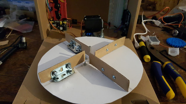
Here we will need the workings wired up. I have mounted a tray made out of wax cardboard with a cd for added support onto a plastic sprocket that has a plastic chain and is turned by a continuous rotation motor (about 6 volts). I used spacers to raise the table so it does not tangle knocking the chain off. Here is a picture the first setup with a small cable instead of chain=>.


 Here is a more recent picture with the sprocket and chain added:
After I was happy with the table I then moved on to the PIR motion sensor. This sensor, located on the
front of the box will detected a person walking in front the box, relay a signal to the Raspberry Pi and thus will active the screen of the system. (I am not fully sure whether it will be operated by the Arduino yet since the Arduino has an analog to digital converter which could possibly rule out an false readings by averaging out where as the Pi can only read high or low digital values and may not get a full accurate reading. But we will see. Here are pictures of the PIR motion sensor mounted to the box:


Next I have added an LED seven segment display in order to give an accurate display of the current tray that is at the opening. I also just kinda thought it was cool and had worked with one already.
Here are pictures of the Seven Segment Display:


After a few updates to the Tray, the mounting of the Arduino, and the external power port, below are the pictures where it currently stands.




Part 2 in new blog.
Now, I'm back. I watched an inspirational Ted Talk a few weeks ago, about how the future of computers, IoT devices, and technology in general should start to take a turn. How we, as creators, should think towards devices that we do less on and react more to our own gestures, habits, and needs. So, I decide to begin work on an Idea I have dubbed "Project Closet v.1". Project Closet v.1 is an interactive storage idea. The prototype itself may be rather modest but the idea has limitless bounds. The idea is that the storage system can react to you when you are around, or turn on, and show you a list (pictures) of items inside, and deliver one to you if you press the picture. Sounds simple but if it is implemented as a large pantry of food could do several things. It could present you with a meal idea based on what is inside, or alert when you are out of an item. Maybe it could even find the item on shopping sites such as amazon and order it for you if it learned you didn't like to be out. It could alert you when food is near expiration or you could check the items inside when you were on the go. It could keep an accurate list of what you have purchased over time and recommend better prices on common items. Maybe it is a simple night stand storage box, with a charger area for your phone, a place for your wallet and keys. It could alert you when you may forget an item in the mourning or wake you up presenting your medications or vitamins. Like I said, it is an idea limited only by the creator imagination.
I began work a few weeks back on a simple prototype using the Raspberry Pi B+ and the Arduino. I can break this idea down into a few categories, This is the first part:
The box*

Here we will need the workings wired up. I have mounted a tray made out of wax cardboard with a cd for added support onto a plastic sprocket that has a plastic chain and is turned by a continuous rotation motor (about 6 volts). I used spacers to raise the table so it does not tangle knocking the chain off. Here is a picture the first setup with a small cable instead of chain=>.


 Here is a more recent picture with the sprocket and chain added:
After I was happy with the table I then moved on to the PIR motion sensor. This sensor, located on the
front of the box will detected a person walking in front the box, relay a signal to the Raspberry Pi and thus will active the screen of the system. (I am not fully sure whether it will be operated by the Arduino yet since the Arduino has an analog to digital converter which could possibly rule out an false readings by averaging out where as the Pi can only read high or low digital values and may not get a full accurate reading. But we will see. Here are pictures of the PIR motion sensor mounted to the box:


Next I have added an LED seven segment display in order to give an accurate display of the current tray that is at the opening. I also just kinda thought it was cool and had worked with one already.
Here are pictures of the Seven Segment Display:


After a few updates to the Tray, the mounting of the Arduino, and the external power port, below are the pictures where it currently stands.


Part 2 in new blog.
Saturday, February 13, 2016
Raspberry Pi 2 Seven Segment Display project 2
Here I have used the same code from the previous LED countdown project only changing the output pins used and have wired up a single 7 segment common cathode led display. I used 330 ohm resistors to each led in the and wired both middle pins on the display to ground. Below are pictures and a video. Enjoy.


Learning Pi programing in python, Led Project 1
Today I finally finish a slightly simple led project with my Raspberry Pi 2. First, let me start by explaining the why. In our mid term project class for computer science we were tasked with creating an interesting Led circuit using at least 6 LEDs, the GPIO pins, and a program we had written in python. After muddling around a few ideas, I chose to do a countdown using 11 LEDs and 1 rgb LED (red, green blue). The LEDs are a mix of red and yellow because at the moment that is all I have.
Below a few pictures, a screen shot of the code, and a video. Enjoy.


Below a few pictures, a screen shot of the code, and a video. Enjoy.


In the video, 7 and 3 are backwards. I have changed them in the shown code. Really just an FYI.
Saturday, January 23, 2016
Setting up Raspberry Pi 2 B+ with Ubuntu Arm
After working my way through daunting tasks while setting up my Raspberry Pi 2 B+ with Ubuntu Arm. I figured they may be other people who want to work their way through these problems so here is a post that I hope helps you all.
First step is to decide which operating system you want to use. The raspberrypi.org has a host of OS downloads and you can find them here: https://www.raspberrypi.org/downloads/.
I however did not get my program from this page and I am instead running Ubuntu 14.04.3 which was a little be more tedious to set up and unless you have a particular reason to go this route i.e (ROS/Robot Operating System support) then I would recommend doing something more simple. Again, I would stress another route. Secondly when you decide which operating system you would like you then need to have a microSD card ready to put the image file (IO) onto. Most recommend at least 8gig size but the larger the better.
You will then need to download Win32 disk imager in order to make your SD card ready to be installed once placed in the Pi. You can find this download here: http://sourceforge.net/projects/win32diskimager/. Be very careful when doing this process for if you select the wrong drive to image you could wipe whatever drive you select. I would recommend unhooking all usb drives and extra memory cards you may have hooked to the computer you are using to do the imaging. Then I would recommend opening your "mycompter" folder or whatever Mac OS equivalent you have and taking a look at the correct drive label of the SD card you are going to image. Then open up the imager and follow the directions.
After this is done you can eject the sd card from your computer and place it in your pi. Hook up your monitor, keyboard, and mouse and then power it up.
If no connection is registered on your monitor and nothing shows up, you can fix this by putting the sd card back into you computer and navigating your way to the config.txt file on the sd. I believe it can be located first page as soon as you open up the sd. You can simply uncomment the code where it says HDMI_Mode=1 and HDMI_Force_Hotplug=1 by removing the #'s. A better solution, as this may cause the desktop to not auto detect the ratio need for the monitor, would be to find out the model of your monitor or at least the correct resolution and refresh rate and follow the directions here: https://www.raspberrypi.org/documentation/configuration/config-txt.md. Over-clocking your Rasp Pi (making it run faster) can also be done by editing this file. (using nano, a command line text editor.)
In the command line, type the following:
sudo nano /boot/config.txt
enter your password.
Then when the file pops up, somewhere in the file, (preferably and empty space area) add the following.
arm_freq=1000
core_freq=500
sdram_freq=500
over_voltage=2
then press ctrl + shift + O to write (save) to the file
then press ctrl + shift + X to exit the file, then reboot by typing
sudo reboot
If you end up going the route I did and install the same Ubuntu then the directions and download for this can be found here: https://wiki.ubuntu.com/ARM/RaspberryPi. Everything is done using the command line so it can get a little uncomfortable if you are not familiar with Linux.
It it easier to follow along with this video ---> https://www.youtube.com/watch?v=UGSQ7nzVCs4
he does a very good job explaining everything. Follow those directions and you will be fine. When the guy says you can use any text editor you want but he then uses mg, I would recommend avoiding that editor and instead using nano which is a text editor you can access from the command line. (sudo nano "fileExtension") Warning, it will take awhile. I would recommend just doing one of the simple installations of an OS from raspberrypi.org.
Finally, for those who are having issues with the ridiculous slow moving mouse pointer. First navigate to your mouse settings and speed them all the way up. Then, all you have to do is open up the command line. You will then edit the cmdline.txt file located in your /boot folder.
follow these instructions. type:
sudo nano /boot/cmdline.txt
add this anywhere in the file:
usbhid.mousepoll=0
then press ctrl + shift + O to write (save) to the file
then press ctrl + shift + X to exit the file, then reboot by typing
sudo reboot
That should get you started. If anyone has any questions feel free to ask. I may not have all the answers but Ill try to help you through your issue.
First step is to decide which operating system you want to use. The raspberrypi.org has a host of OS downloads and you can find them here: https://www.raspberrypi.org/downloads/.
I however did not get my program from this page and I am instead running Ubuntu 14.04.3 which was a little be more tedious to set up and unless you have a particular reason to go this route i.e (ROS/Robot Operating System support) then I would recommend doing something more simple. Again, I would stress another route. Secondly when you decide which operating system you would like you then need to have a microSD card ready to put the image file (IO) onto. Most recommend at least 8gig size but the larger the better.
You will then need to download Win32 disk imager in order to make your SD card ready to be installed once placed in the Pi. You can find this download here: http://sourceforge.net/projects/win32diskimager/. Be very careful when doing this process for if you select the wrong drive to image you could wipe whatever drive you select. I would recommend unhooking all usb drives and extra memory cards you may have hooked to the computer you are using to do the imaging. Then I would recommend opening your "mycompter" folder or whatever Mac OS equivalent you have and taking a look at the correct drive label of the SD card you are going to image. Then open up the imager and follow the directions.
After this is done you can eject the sd card from your computer and place it in your pi. Hook up your monitor, keyboard, and mouse and then power it up.
If no connection is registered on your monitor and nothing shows up, you can fix this by putting the sd card back into you computer and navigating your way to the config.txt file on the sd. I believe it can be located first page as soon as you open up the sd. You can simply uncomment the code where it says HDMI_Mode=1 and HDMI_Force_Hotplug=1 by removing the #'s. A better solution, as this may cause the desktop to not auto detect the ratio need for the monitor, would be to find out the model of your monitor or at least the correct resolution and refresh rate and follow the directions here: https://www.raspberrypi.org/documentation/configuration/config-txt.md. Over-clocking your Rasp Pi (making it run faster) can also be done by editing this file. (using nano, a command line text editor.)
In the command line, type the following:
sudo nano /boot/config.txt
enter your password.
Then when the file pops up, somewhere in the file, (preferably and empty space area) add the following.
arm_freq=1000
core_freq=500
sdram_freq=500
over_voltage=2
then press ctrl + shift + O to write (save) to the file
then press ctrl + shift + X to exit the file, then reboot by typing
sudo reboot
If you end up going the route I did and install the same Ubuntu then the directions and download for this can be found here: https://wiki.ubuntu.com/ARM/RaspberryPi. Everything is done using the command line so it can get a little uncomfortable if you are not familiar with Linux.
It it easier to follow along with this video ---> https://www.youtube.com/watch?v=UGSQ7nzVCs4
he does a very good job explaining everything. Follow those directions and you will be fine. When the guy says you can use any text editor you want but he then uses mg, I would recommend avoiding that editor and instead using nano which is a text editor you can access from the command line. (sudo nano "fileExtension") Warning, it will take awhile. I would recommend just doing one of the simple installations of an OS from raspberrypi.org.
Finally, for those who are having issues with the ridiculous slow moving mouse pointer. First navigate to your mouse settings and speed them all the way up. Then, all you have to do is open up the command line. You will then edit the cmdline.txt file located in your /boot folder.
follow these instructions. type:
sudo nano /boot/cmdline.txt
add this anywhere in the file:
usbhid.mousepoll=0
then press ctrl + shift + O to write (save) to the file
then press ctrl + shift + X to exit the file, then reboot by typing
sudo reboot
That should get you started. If anyone has any questions feel free to ask. I may not have all the answers but Ill try to help you through your issue.
Subscribe to:
Posts (Atom)